| View previous topic :: View next topic |
| Author |
Message |
Duval JP
Joined: 22 Jun 2004
Posts: 1231
Location: France

|
 Posted: Wed Jul 03, 2024 5:12 pm Post subject: Posted: Wed Jul 03, 2024 5:12 pm Post subject: |
 |
|
Hi
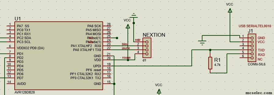
It's is working well for me : CP2102n VCC=5V with filtering/decoupling capacitors 1µf and 10nF
And
and
JP 
_________________
pleasure to learn, to teach, to create |
|
| Back to top |
|
 |
ulfbc
Joined: 12 Mar 2019
Posts: 23

|
| Posted: Wed Jul 03, 2024 6:11 pm Post subject: |
|
|
| programmista123 wrote: | Hello,
Could you try with lower speed? For example 9600.
With CP2102 I can reach 19200 max.
Regards,
Przemek
Edit: I'm using 100 timeout setting, DTR-pin: none. |
not that low speed - will try tomorrow
@Duval:
thanks for your input. I've ordered a FTDI Adapter. So I will try this with this Hardware. Should arrive tomorrow |
|
| Back to top |
|
|
albertsm
Joined: 09 Apr 2004
Posts: 6303
Location: Holland

|
| Posted: Wed Jul 03, 2024 7:47 pm Post subject: |
|
|
JP that is the AVRX series which can work on higher baud.
the xtiny is limited to 900 KHz. so i suggest 115200 baud first.
the protection resistor can be 1K. but only function is to protect the TX.
the voltage is also important. try 5V if possible.
and then of course : is the usb power used to power the circuit?
do all gnd and vcc have a connection?
you best provide more details. cp2102 works best for me.
my timeout is 30.
for the best hardware : get yourself a SNAP programmer from Microchip, it will be supported in the next update.
_________________
Mark |
|
| Back to top |
|
|
ulfbc
Joined: 12 Mar 2019
Posts: 23
|
| Posted: Thu Jul 04, 2024 8:36 pm Post subject: |
|
|
now works fine with a FTDI232 Adapter
thanks to Przemek, JP and Marc
Regards
Ulf
ps:
and with CP2102 Adapter as well.
Both wit 1K Resistor between TX and TX |
|
| Back to top |
|
|
ulfbc
Joined: 12 Mar 2019
Posts: 23
|
| Posted: Fri Jul 05, 2024 1:28 pm Post subject: |
|
|
| The CP2102 is flashing faster. Both driven with 225kBd. |
|
| Back to top |
|
|
EDC
Joined: 26 Mar 2014
Posts: 1180

|
| Posted: Fri Jul 05, 2024 2:08 pm Post subject: |
|
|
| albertsm wrote: | | for the best hardware : get yourself a SNAP programmer from Microchip, it will be supported in the next update. |
@albertsm did you notice that Microchip release SNAP PCBv2 (with new jumper) that have issues with the old Studio and preffer the MPLAB?
Problem described on the polish forum and confirmed by another user.
https://www.elektroda.pl/rtvforum/topic4061309.html
I hope that commandline was not altered.
_________________
Check B-Flash -my MCS bootloader app for Android |
|
| Back to top |
|
|
albertsm
Joined: 09 Apr 2004
Posts: 6303
Location: Holland
|
| Posted: Sat Jul 06, 2024 12:21 pm Post subject: |
|
|
did not know. but for microchip they are the same. i do not see how i could get such a new pcb v2 to test?
does this snap has a different usb product id?
well my implementation should work anyway. i wonder about the resistor too. you still need to remove a resistor ? (forgot which one it was)
_________________
Mark |
|
| Back to top |
|
|
matjazs
Joined: 08 Nov 2016
Posts: 124
|
|
| Back to top |
|
|
programmista123
Joined: 31 Jan 2018
Posts: 204
|
| Posted: Tue Jan 14, 2025 8:27 am Post subject: |
|
|
Hi,
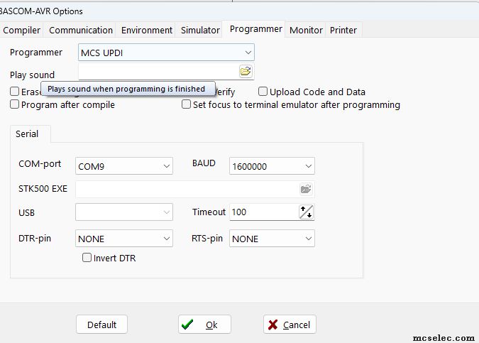
Could you share programmer options screenshot?
Do you have any errors? |
|
| Back to top |
|
|
Duval JP
Joined: 22 Jun 2004
Posts: 1231
Location: France
|
| Posted: Tue Jan 14, 2025 11:29 am Post subject: |
|
|
interesting.
but is it faster than programming with a CP2102?
jp
_________________
pleasure to learn, to teach, to create |
|
| Back to top |
|
|
EDC
Joined: 26 Mar 2014
Posts: 1180
|
| Posted: Tue Jan 14, 2025 11:41 am Post subject: |
|
|
CH340 is not a speed demon  but it is nomather if it is faster. but it is nomather if it is faster.
When you lock AVR with UPDI you need a 12V pulse to unlock it.
I think even SNAP cant do that.
On the shop site there is a link to oryginal design for this tool so I read documentation. 12V pulse is controlled by RTS signal. It must be low to drive PNP transistor.
Bascom can handle both DTR and RTS signals but only DTR can be inverted as option.
I dont know on which state is RTS signal "normally".
Maybe there is a permanent low state and this tool inject 12V over that PNP transistor so communication cannot be established.
Regardless I order one this little baby for tests
_________________
Check B-Flash -my MCS bootloader app for Android |
|
| Back to top |
|
|
matjazs
Joined: 08 Nov 2016
Posts: 124
|
| Posted: Tue Jan 14, 2025 8:13 pm Post subject: |
|
|
| programmista123 wrote: | Hi,
Could you share programmer options screenshot?
Do you have any errors? |
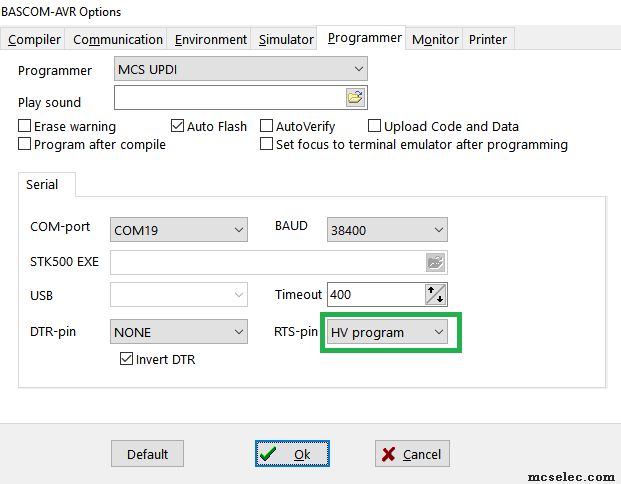
Screenshots are attached. The error is the same with all other option settings (DTR-pin, RTS-Pin >> program/data,HV program, NONE) |
|
| Back to top |
|
|
JC
Joined: 15 Dec 2007
Posts: 643
Location: Cleveland, OH

|
| Posted: Tue Jan 14, 2025 9:53 pm Post subject: |
|
|
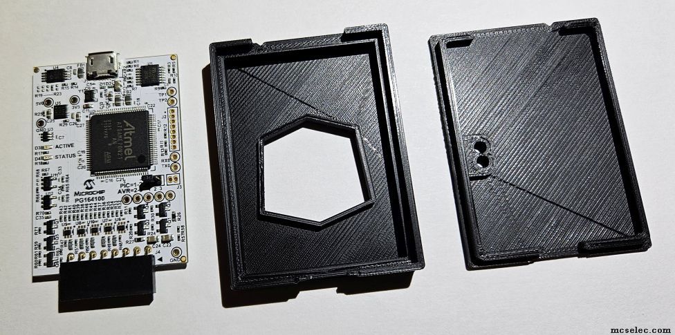
Above Mark asked about the SNAP V1 and V2 VIDs.
I have both SNAP versions.
The new SNAP V2 has a small 3-Pin header on the SNAP PCB.
It is seen in the photo below, just below the microcontroller chip.
Shorting 1 and 2 is for PICs.
Shorting 2 and 3 is for AVRs.
I've used my SNAP V2 for SPI so far, but I've not yet tested it on an Xmega (PDI), or a UPDI chip.
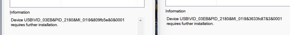
When I plug the V1 and V2 SNAPs into my Windows PC, I see the following VID info in the Device Manager.
The LEFT info is V2, the RIGHT info is the V1 SNAP.
(The 3D case file / design was on Thingiverse, by ariz0na.)
JC
 |
|
| Back to top |
|
|
EDC
Joined: 26 Mar 2014
Posts: 1180
|
| Posted: Thu Jan 23, 2025 12:27 pm Post subject: |
|
|
Okay, I got it today. I order it from linked store to be precise.
It is funny for me that it comes with three pin connector JST on the board and four pin plug ahahahaha. So the plug with the wires are useless.
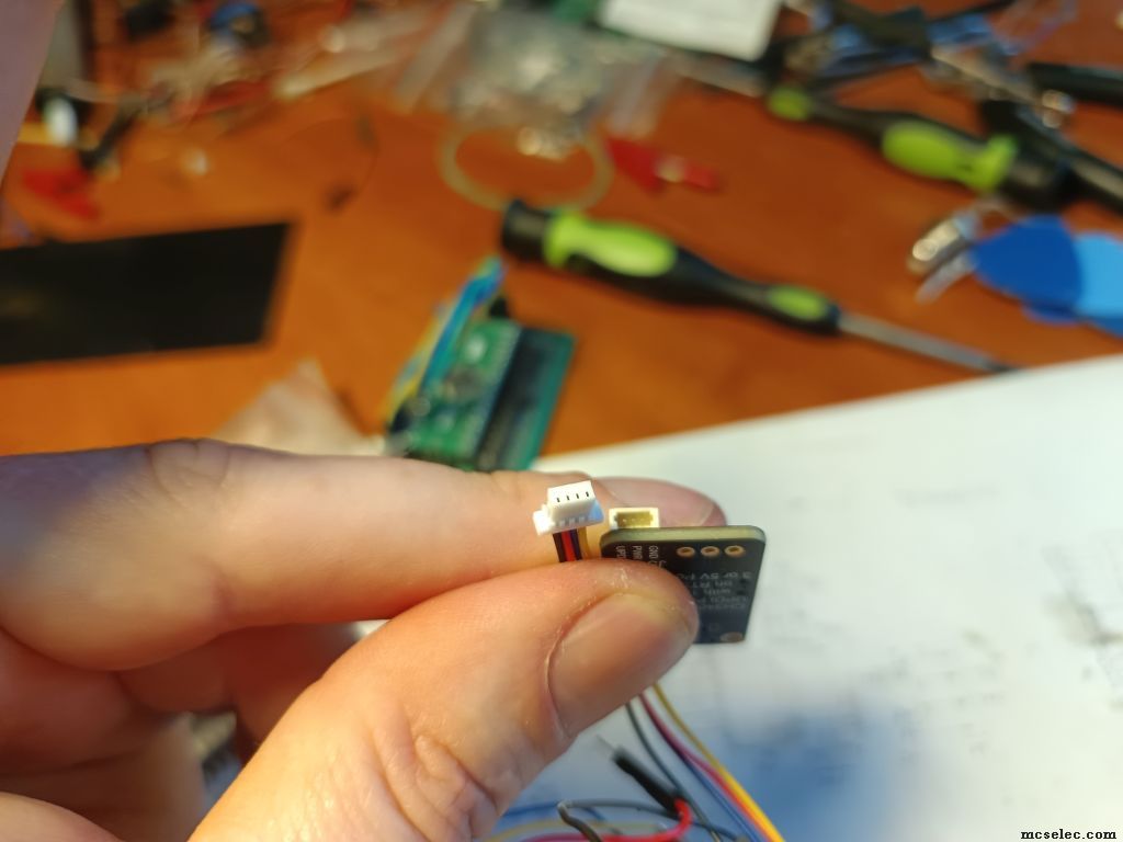
Nomather that I solder a golpin connector (not attached) and connect it to my AVR128DB32 because it is the shortest way to me with this board.
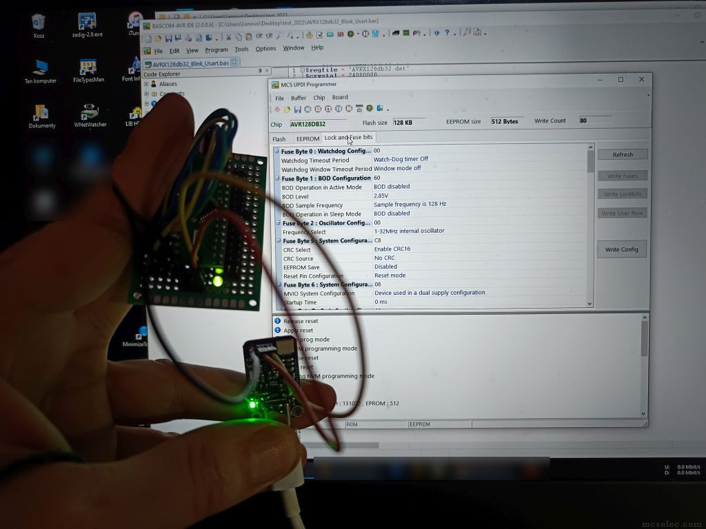
Everything looks like working fine. I can connect and read FuseBits.
I will check the 12V function later.
Please check your connections if you have problem with this adapter. It is working for me.
_________________
Check B-Flash -my MCS bootloader app for Android |
|
| Back to top |
|
|
EDC
Joined: 26 Mar 2014
Posts: 1180
|
| Posted: Thu Jan 23, 2025 1:12 pm Post subject: |
|
|
Okay, I test it because Im curious about everything from the birth.
Bascom doing this well. Voltage stays at 5V with this tool.
Only when you config a RTS signal as HV programm then pulse is present at the begining of the sequence.
I set trigger (on oscilloscope) above 5V and rest of communication is 5V-0V shorting to ground.
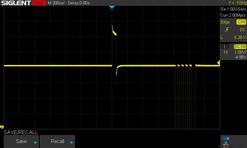
Now I see that I measure something last time x1 not x10 probe today (This is my fault but not the case here).
_________________
Check B-Flash -my MCS bootloader app for Android |
|
| Back to top |
|
|
|


